In the previous post — “Using modbus-cli to Read and Write Modbus Coils in LabShock” — I showed something simple:
We were able to read and write Modbus coils… with no authentication.
In this part, I continued the experiment inside LabShock (OilSpring Air lab), but instead of coils, I focused on actual process values—and also writing directly to registers.
The Setup (Operator View)
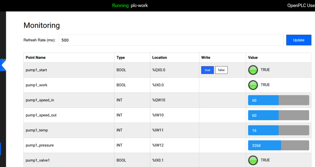
From the OpenPLC monitoring dashboard, everything looks clean:
pump1_speed_in → %QW10 → 50pump1_speed_out → %IW10 → 50pump1_temp → %IW11 → 16pump1_pressure → %IW12 → 3158
You just see:
- Speed
- Temperature
- Pressure
That’s the operator view.
Reading via Modbus (What We Did)
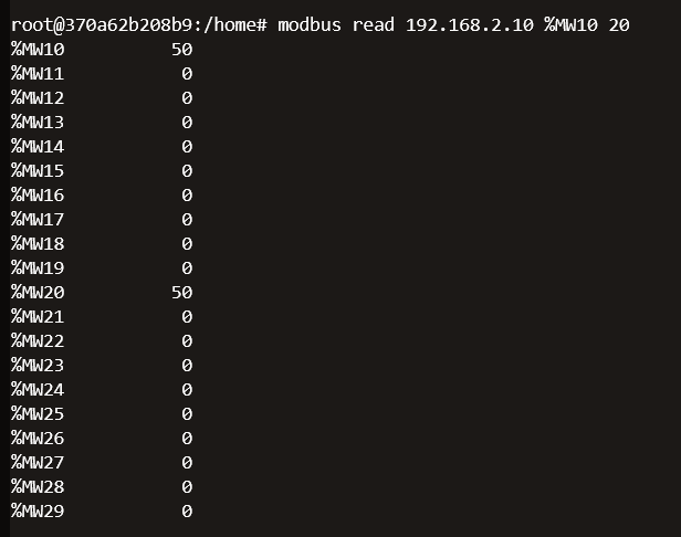
After installing modbus-cli, I ran:
modbus read 192.168.2.10 %MW10 20
Quick breakdown:
modbus read→ read from device192.168.2.10→ PLC IP%MW10→ start from memory word 1020→ read 20 values
So we dump:
%MW10 → %MW29
What We Got
From the output:
%MW10 = 50%MW20 = 50- others mostly
0
One command → raw memory view.
Making Sense of %QW, %IW, %MW
%QW10 → Output
What the PLC sends (e.g., pump speed)
%IW10 → Input
What the PLC reads (sensor values)
%MW10 → Memory
Internal storage used by the program
Why We Saw Those Values
Even though the dashboard shows %QW and %IW, we read %MW.
That’s because PLC logic often copies values internally:
%QW10 → %MW10
%IW10 → %MW20
So:
We didn’t read outputs or inputs directly—we read their copies.
Writing to a Register (New Part)
Now the important part.
We didn’t just read—we also wrote to memory.
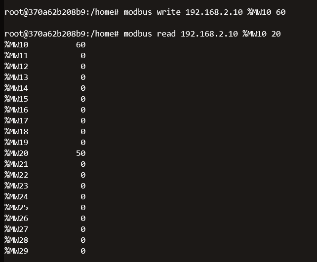
modbus write 192.168.2.10 %MW10 60Breaking It Down
modbus write→ send value to PLC192.168.2.10→ PLC IP%MW10→ target register (memory word 10)60→ value to write
So:
Write value 60 into memory address
%MW10
What Happens After Writing
If you check:
- OpenPLC dashboard (or SCADA in LabShock)
You will see the value change.
To confirm from CLI:
modbus read 192.168.2.10 %MW10 1
This reads only one value.
You should now see:
%MW10 = 60
Why This Is Important
This is not just reading anymore.
This is:
Direct modification of PLC data
Depending on the logic, this could:
- Change setpoints
- Affect process behavior
- Influence outputs indirectly
Operator vs What We Did
| Operator | What We Did |
|---|---|
| Uses dashboard | Used Modbus CLI |
| Sees values | Reads raw memory |
| No direct memory access | Full access |
| Controlled UI | No restrictions |
What This Proves
This reinforces the same point as Part 1:
Modbus is not secure by design.
We were able to:
- Read process values
- Dump memory
- Write to registers
- Write to coils (Part 1)
All of this:
- No authentication
- No encryption
- No validation
Why This Matters
1. Read = Recon
You can map the system just by reading.
2. Write = Impact
You can influence the system by writing.
3. No Barriers
If you can reach the PLC:
You can interact with it.
What Defenders Should Take From This
- Restrict Modbus access (segmentation is critical)
- Monitor read activity, not just writes
- Understand what each register exposes
- Treat internal memory as sensitive
Final Thought
Part 1 showed we can control coils.
Part 2 shows we can read and modify process values.
When a protocol lets you read and write critical data with no authentication,
that’s not a misconfiguration — that’s the design.
And once you see that layer,
you’re no longer looking at the system like an operator…
you’re seeing it like an attacker.